Refrigeration Cycle Research
Detailed below is a summarization of the research complied for each of the four components of the Refrigeration Cycle at the Campus Chiller Plant.
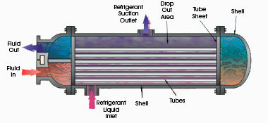

The Evaporator
The first stage that we will take a closer look at is the Evaporator. When the refrigerant reaches the evaporator, it comes into the evaporator as a two-phase liquid-vapor mixture. What is a two-phase liquid vapor mixture? In short, it is a combination of saturated liquid and saturated vapor. A saturated liquid is any liquid that if the pressure of the liquid is decreased at all, it will cause the liquid to boil. A saturated vapor is when a system has the maximum amount of vaporized water, and the addition of anymore vapor into the system will cause condensation to start. However, in the system at the Campus Chiller Plant, wet compression is not used as the presence of liquid can severely damage the compressor. The Evaporator is the part of the Refrigeration Cycle that does the actual cooling, meaning that “it’s function is to absorb heat into the refrigeration system” (Yeh). Put another way, “The evaporator is a heat exchanger that removes the building heat from the chilled water lowering the water temperature in the process. The heat is used to boil the refrigerant changing it from a liquid to a gas” (McQuay). Within the evaporator, some of the refrigerant is converted into a vaporized form. The vaporization of the refrigerant is caused by the heat being absorbed from the environment around the evaporator through a fain boiling the air through a coil. This was the part of the evaporator that was exposed at the campus chiller plant. Metal ‘finned’ tubes with a high heat capacity are zig-zagged throughout the condenser to absorb the heat. “The fins and tubes are made of metals with high thermal conductivity to maximize heat transfer. The refrigerant vaporizes from the heat it absorbs heat in the evaporator,” (Yeh). In an ideal Carnot Refrigeration Cycle, the temperature and pressure of the refrigerant remain constant in the evaporator. However, the Campus Chiller plant is not an ideal system. Because the heat transfer within the evaporator is not a reversible process, the temperature of the refrigerant in the evaporator must be “several degrees below the cold region temperature” (Textbook). With this taken into account, the coefficient of performance will decrease. The vaporized refrigerant (R134a) moves to the compressor as high temperature and low pressure vapor.
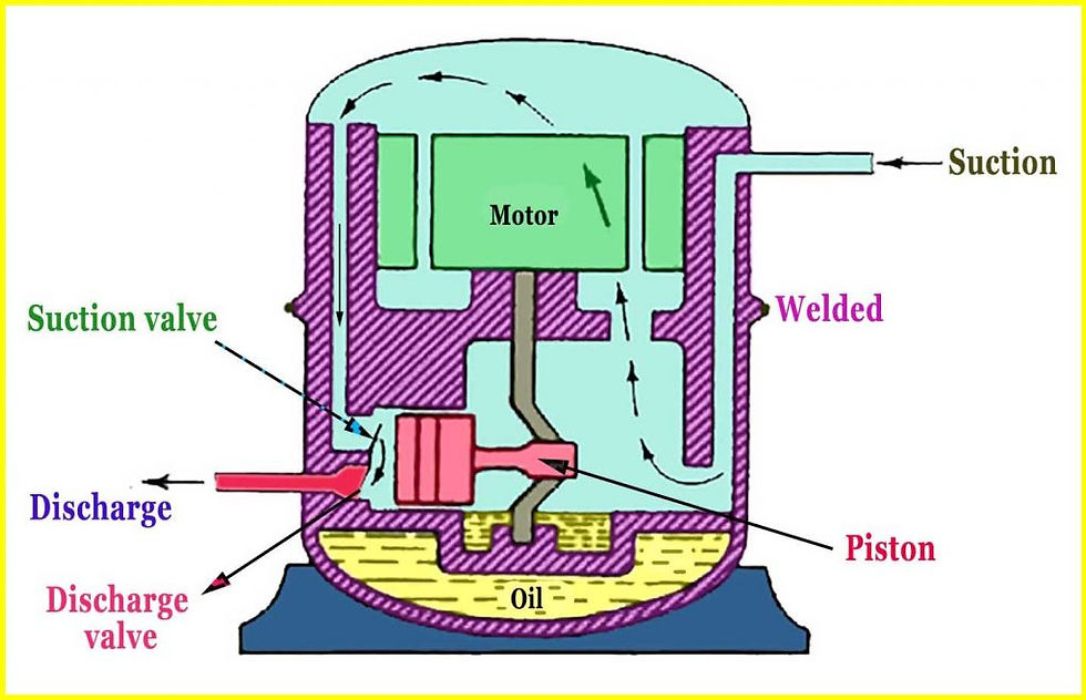

The Compressor
The next stage of the Refrigeration Cycle is the compressor. Within the compressor, the gas is compressed, adiabatically, from a low pressure to a high pressure. The highest pressure must match the pressure setting on the evaporator, which would be part of the specifications for the given evaporator used at the Oak Street Campus Chiller plant. Within the compressor, there is usually a piston-motor system that drives the flow of the low pressure vapor to the high pressure vapor. At a more in-depth view, the piston, driven by a motor, causes the piston to move within a cylinder. When piston moves in such a way that the volume of the cylinder expands, it causes the refrigerant to be sucked in due to a pressure difference. “The intake valve closes when the refrigerant pressure inside the cylinder reaches that of the pressure in the evaporator” (Yeh). What this means is that once the pressure within the cylinder matches the incoming evaporated refrigerant, the compressor will stop the intake of the refrigerant. The piston then moves back down the cylinder compressing the vaporized refrigerant to a higher pressure. This high pressure vapor is then released out of the compressor, through an exhaust valve, to move forward in the process to the condenser. The cycle within the compressor continues on a continuous cycle, sucking in the low pressure gas from the evaporator through the motion of the piston, and then the piston pushing and compressing the vapor to a higher pressure and evacuating it to the condenser. Because the vapor is now at a higher pressure, the Ideal Gas Law relationship developed in class states that the temperature must also increase. At this portion of the process, work is being inputted into the system in order to drive the compressor and the motor-piston system within the compressor.
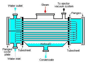

Condenser from Oak Street Chiller Plant
The Condensor
The next stage of the Refrigeration Cycle is the Condenser. The condenser is another heat exchange component within the cycle. The purpose of the condenser is to remove heat from the refrigerant that it picked up from being evaporated in the evaporator stage of the cycle. The refrigerant vapor enters the condenser as a high temperature high pressure vapor and releases heat as it is exposed to a cooling medium, usually air-cooled or water-cooled. “As heat is removed from the vapor, a change of state takes place and the vapor is condensed back into a liquid” (Berg). In this stage and throughout the entire process, the refrigerant is still a saturated liquid and saturated vapor in the various stages. As mentioned above, as the heat is removed from the refrigerant to the surroundings, the refrigerant is converted back into the saturated liquid form and ready to move through the expansion valve to the evaporator. Within the condenser, it is important to understand what exactly is going on. The condenser is also comprised of fins and metal tubing, similar to the evaporator. As the refrigerant is forced to move through the condenser, the cooling medium (water) surrounds the refrigerant and absorbs the heat given off by the condensed refrigerant vapor and then takes it to the cooling tower. The pressure and temperature ideally remain constant, however the refrigerant must obtain a higher temperature by a few degrees than the warm region in order to sustain an adequate amount of heat transfer. Like the evaporator, the other heat transfer device, the coefficient of performance will decrease due to the higher temperatures being required to obtain the necessary heat transfer.
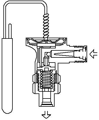


The Expansion Valve
The final stage of the Refrigeration Cycle is the Expansion Valve. At the campus chiller plant, the expansion valve is an Orifice Plate. The purpose of the expansion valve is to reduce the pressure, and subsequently, the temperature of the Refrigerant after it has been condensed back into a liquid form and also restrict the flow of the fluid to the evaporator. The liquid refrigerant comes in as a high pressure liquid, and after going through the Orifice Plate, has been reduced to a pressure more suitable for the evaporator. The refrigerant enters the evaporator through the coils, as described earlier, and the cycle begins all over again. One important thing to note is that little to no refrigerant is lost during the cycle unless there is a leak. Therefore, the refrigerant may be reused for many cycles until the parameters indicate it needs to be replaced, if ever.